Load rating and bearing life
Size of the bearing that will be used in a particular solution is at first selected basing on: bearing’s load rating in relation to loads that are occurring, requirements on service life and reliability. Nominal rating values of basic static load C0 and basic dynamic load C has been provided in the charts.
In bearing technology both static and dynamic load conditions has to be independently checked.
In bearing technology both static and dyna- mic load conditions has to be independently checked (n < 10 rev/min). For such loads the safety regarding plastic deformations (due to contact stresses) at raceways and rolling elements contact point is checked.
In dynamically loaded bearings rings are rotating with relation to each other. In that instance the safety factors regarding fatigue of raceway and rolling elements material is also taken into consideration beside plastic deformation.
Fatigue occurring on rolling surfaces is the main cause of bearings failure.
Static load
Static load occurs when bearings:
- are under load and stationary for a long period of time,
- are rotating very slowly (n < 10 rev/min),
- are performing slow oscillating movements.
Verification of bearing static load is made by checking static safety factor, described by formula:

where:
s0 – static safety factor,
C0 – basic static load rating [N],
P0 – equivalent static bearing load [N].
The s0 coefficient is a measure of safety with regard to plastic deformations at contact points between rings and rolling elements. High static safety factor is necessary for bearings that has to be easy to rotate and work quietly. Lower values are satisfactory when requirements for silent running are not so important.

Static load rating C0 for FLT bearings was elaborated according to ISO 76 standard. Acc. to this standard static load rating is the load which causes contact stress occurrence in the centre of the most loaded area of contact point of rolling element with raceway. It has the following values:
- 4600 4600 MPa for self aligning ball bearings,
- 4200 MPa for other types of ball bearings,
- 4000 MPa for roller bearings,
however for radial bearings it is static radial load – basic static radial load rating; and for thrust bearings it is static axial load applied to bearing’s axis – basis static axial load rating. For those contact stresses the total permanent deformation of the most loaded rolling element and raceway has the size of aprox. 0,0001 of rolling element diameter.
Equivalent static bearing load
Static load which consist of radial and axial loads has to be converted to equivalent static bearing load.
Equivalent static bearing load P0 is a static load (radial for radial bearings and centralaxial for thrust bearings) which would cause the same contact stresses to occur in the centre of the most loaded area of raceway and rolling element contact point as real life complex force system.
Equivalent static bearing load can be calculated using general formula:

where:
P0 – equivalent static bearing load [N],
Fr – radial bearing load (= radial component of real bearing load), [N],
Fa – axial bearing load (= axial component of real bearing load), [N],
X0 – static radial load factor,
Y0 – static axial load factor.
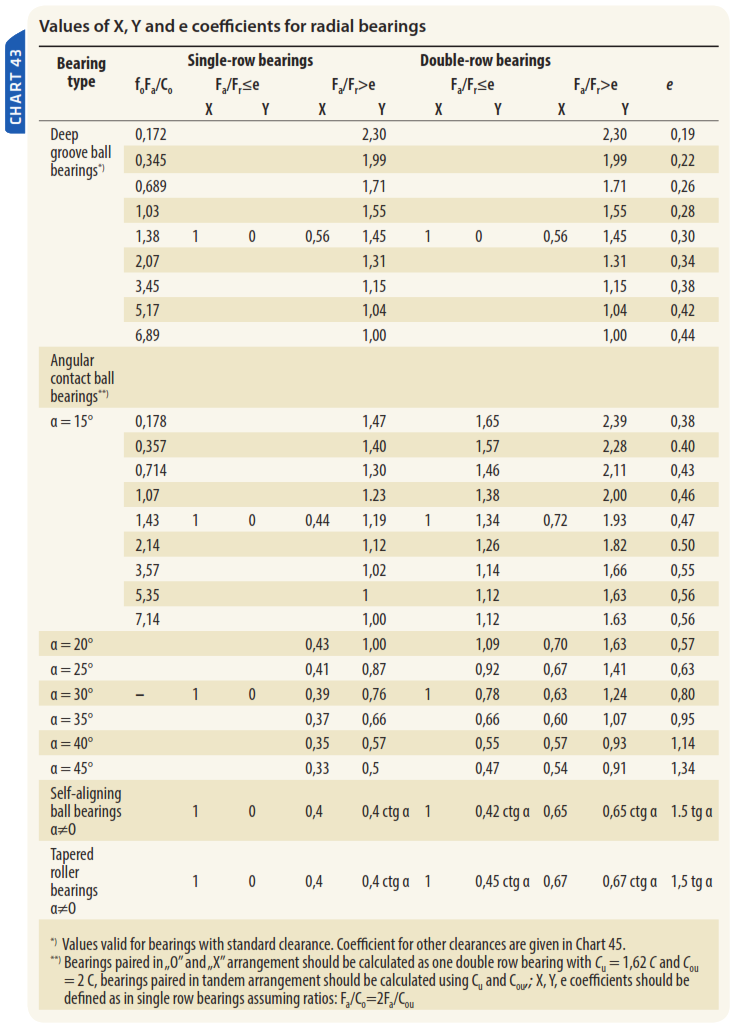
Values of X0 and Y0 coefficients can be read from charts in the further part of this publication.
Dynamic loads and bearing life
For calculations of dynamically loaded bearings i.e. bearings that are rotating under load, the basic dynamic load rating Cis used. This quantity is a constant (as for value and bearing load direction) at which bearing will achieve nominal service life of one million revolutions acc. to ISO 281 standard, providing that for radial bearing the load is purely radial – basic dynamic radial load rating, and for thrust bearings the load is purely axial – basic dynamic axial load rating. Values of load rating presented in this publication are regarding to bearings manufactured from bearing steel, hardened till at least 58 HRC. Bearing service life can be defined as particular number of revolutions or as number of worked hours which bearing is capable to achieve till first signs of fatigue wear (scoring, spalling) on one of the rings or on rolling elements.
Basic rating life
Basic rating life of a bearing is the life that corresponds to 90% reliability using standard material and manufacturing quality at a normal operating conditions.
According to ISO 281 standard the following formula is used for calculations:

where:
L10 – basic rating life (at 90% reliability),[millions of revolutions],
C – basic dynamic load rating [N],
P – equivalent dynamic bearing load [N],
p – exponent for the life equation
= 3 for ball bearings,
= 10/3 for roller bearings.
The equation for othe raliability than 90% have the following form:

where:
Ln – basic rating life for reliability ≠ 90%, [milions of revolutions],
a1 – life modication factor for reliability, acc. to Chart 40,
L10 – basic rating life (at 90% reliability),[millions of revolutions]
Dynamic equivalent bearing load
Dynamic equivalent bearing load is a load of constant value and direction (radial in case of radial bearings – dynamic equivalent radial load, or axial in case of thrust bearings – dynamic equivalent axial load) under which the bearing would achieve the same life as under acting complex system of loads.
Dynamic equivalent bearing load under constant radial and axial loads have the following form:

where:
P – equivalent dynamic bearing load, [N],
Fr – radial bearing load (= radial component of real bearing load), [N],
Fa – axial bearing load (= axial component of real bearing load), [N],
X – dynamic radial load factor,
Y – dynamic axial load factor.
The X and Y coefficients values can be found in the charts.
In the instance of bearings working with constant revolutions, bearing life can be expressed in hours using following formula:

where:
L10h – basic rating life in hours, [h],
n – rotational speed, [rev/min],
L10 – basic rating life, [millions of revolutions].
Bearings life, if applied to vehicles, can be expressed in kilometers of mileage using following formula:

where:
L10s – basic rating life in kilometers of mileage, [km],
rd – dynamic tire radius index, [mm],
L10 – basic rating life, [millions of revolutions].
If the bearing is not rotating but performs oscillating movement from middle point for about ±γ angle (Fig. 7) the bearing life can be expressed as follows:

where:
L10o – basic rating life, [millions of cycles],
γ – amplitude of oscillatory movement (angle of max. deflection from middle point), [°],
L10 – basic rating life, [millions of revolutions].
Full oscillation cycle is 4 times γ from point 0 to point 4.

Equivalent rotational speed for bearings that are performing oscillatory movement rather the rotation can be derived by using following formula:

where:
n – equivalent speed of rotation, [rev/min],
γ – amplitude of oscillatory movement, [°],
nosc – oscillation frequency [1/min].
Operating temperature influence on bearing life
The hardness of raceway drops after temperature exceeds 150°C thereby dynamic rating load declines. Dynamic rating load for different temperatures is elaborated by multiplying basic dynamic load rating C by temperature coefficient ft, according to formula:


Influence of hardness on rating load and service life
For rolling bearings with rolling surfaces hard- ness smaller than 58 HRC (Rockwell hardness scale C) the dynamic rating load is elaborated by multiplying basic dynamic rating load C by dynamic load correlation coefficient fH, calculated in simplified form as follows:

where:
fH – dynamic load correlation coefficient,
HRC – Rockwell C hardness of raceway/rolling elements surface.
When hardness value of raceway and/or rolling element contact surfaces is smaller then 800HV (Vickers hardness scale) which is aprox. 63 HRC (in Rockwell hardness scale C), than static rating load is elaborated by multiplying base static load rating C0 by static load correlation coefficient f0H, calculated in simplified form as follows:

where:
f0H – static load correlation coefficient,
f1 – coefficient dependent on contact point type, provided in Chart 39,
HV – hardness of raceway/rolling elements surface in Vickers scale.


Modified life equation
Standard equation of bearing life (L10) has been expanded in order to accommodate fatigue limit and factors connected with lubrication and lubricant contamination.
This modified life equation has been introduced by ISO 281 in the following form:

where:
Lnm – modified life, [millions of revolutions],
a1 – life modification factor for reliability,
aISO – life modification factor,
L10 – basic rating life, [millions of revolutions].
Reliability coefficient
Bearing failures due to fatigue undergo the law of statistic. That is why during bearing life calculation the probability of failure is taken into consideration In general, bearing life is calculated with 10% probability of failure, i.e. for reliability equal to 90%; then the reliability coefficient is equal 1. Values of a1 coefficient for different probabilities are given in the chart below.

Life modification factor aISO
The aISO life modification factor encompass influence of complex factors on rolling bearing fatigue life. Beside bearing type, size, internal geometry and raceways outlines this coefficient includes influence of bearing’s material fatigue stress, lubrication and contamination on bearing life.
Fatigue stress limit
For rolling bearings made from common,high quality materials and according to good manufacturing practices the fatigue stress limit σu is attained at a contact stress of aprox. 1500 MPa. In order to assess fatigue stress limit infl uence on aISO coeffi cient a Cu fatigue load limit is used. It is defi ned as load (radial or axial) at which the σu fatigue stress limit is reached. The Cu fatigue stress limit charts are presented in appropriate charts.
Practical methods of life modification factor evaluation
The aISO life modification factor can be presented as following equation:

where:
eC – contamination factor,
Cu – fatigue load limit, [N],
P – equivalent dynamic bearing load [N],
κ – viscosity ratio.
The eC and κ coefficients take into consideration contamination and lubrication conditions.
Contamination factor
The eC contamination factor takes into consideration decrease of bearing life due to contamination of lubricant by solid particles. Decrease of bearing life caused by solid particles present in lubricant depends on:
- type, size, hardness and particle quantity,
- lubricant film thickness (κ viscosity ratio),
- bearing size.
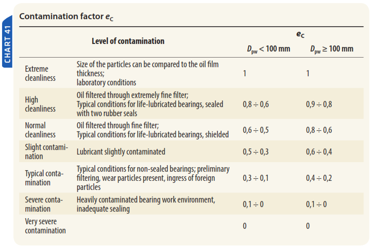
Guide values of contamination factor have been presented in Chart 41, which shows typical levels of contamination for well lubricated bearings. More detailed values can be found on plots and equations in further part of this publication. Those values are valid for mixture of particles with different hardness, in which the hard particles determine the modified durability.
The eC contamination factor is valid only for typical solid particles contaminations. Contamination by water or other fluids that are harmful for bearing life is not considered. In case of severe contamination where eC -> 0, bearing failure may occur due to abrasive wear and operational bearing life might be lower than calculated modified life.
Contaminants classification
Standardized method of contamination level classification of lubricant by solid particles has been described in ISO 4406 international standard. It allows to assess the oil cleanliness class basing on particles count in taken sample. One of the method of oil cleanliness assessment base on counting the amount of particles under the microscope. Two values of cleanliness level which corresponds to particles of sizes ≥ 5 μm and ≥ 15 μm are determined.
The second method utilizes automatic particles count and present results for three sizes of particles: ≥ 4 μm, ≥ 6 μm and ≥ 14 μm.
Three values of cleanliness are obtained after contamination class assessment; for example for oil lubricants it would be −/15/12 or 22/18/13.
Filter rating value βx is a measure that defines filter efficiency – it is the filter capability to stop contaminants of x size [μm]. The greater the βx value is the more efficient the filter is for specified particle size. Due to that fact not only the βx value is important but also the size x of the particles that it corresponds to. Filter rating βx value is described as a ratio of particles of certain size upstream the filter to the quantity of the particles downstream the filter.
The eC value evaluation when contamination level is known
Value of contamination factor is elaborated basing on contamination class or filtering parameters, Dpw mean diameter of bearing’s rolling elements for medium bearing’s diameter dm = 0,5·(d + D) and viscosity ratio κ for given bearing.
Plots (Fig. 9 to 12) that are used for elaboration of contamination factor coefficient for circulating oil lubrication with filtration are valid for different filtration grades and contamination classes. If the level of contamination is constant the similar results can be achieved for filter-less lubrication for example for oil bath lubrication. Nonetheless if the particles amount in oil bath is growing due to wear or foreign particles contamination it DO have influence on eC coefficient for oil bath lubrication.
Plots (Fig. 13 to 17) are used for elaboration of contamination factor coefficient for oil lubrication without filtration or with off-line filter for different contamination classes.
Plots (Fig. 18 to 22) are used for elaboration of contamination coefficient of grease lubricant for different contamination levels that are specified in Chart 42.
Contamination coefficient for circulating oil lubrication with filtering (on-line filters)


Contamination coefficient for grease lubricant


Viscosity ratio
Lubricant selection (oil/grease)
Primarily oil selection is based on viscosity value, which should ensure proper bearing lubrication at operating temperature. Oil viscosity is dependent on temperature and decreases when temperature rises. Oil/temperature dependency is described by viscosity index VI.
Lubricant efficiency depends mainly on rolling contact point separation in the bearing. Lubricant has to posses certain minimal viscosity at operating temperature in order oil film could occur. Lubricating conditions in oil clearance are described by viscosity ratio κ, which is a ratio of actual kinematic viscosity of lubricant in operating temperature to reference kinematic viscosity which ensures proper lubrication.

where:
κ – viscosity ratio,
ν – actual kinematic viscosity of lubricant, [mm2/s],
ν1 – reference (required) kinematic viscosity, [mm2/s].
In order for oil film to develop between working contact surfaces the lubricant has to posses certain minimal viscosity at operating temperature. Bearing life can be extended by increasing operating viscosity v of lubricant.
Reference kinematic viscosity ν1, essential for proper lubrication, can be elaborated from the plot (Fig. 23), dependant from pitch diameter, Dpw (dm mean bearing diameter can also be used) and dependant on n [rev/min]. Reference kinematic viscosity ν1 can also be calculated using the following equations:

for n < 1000 rev/min;
or

for n ≥ 1000 rev/min.

Calculations of κ ratio are based on mineral oils and providing that raceways working surfaces are manufactured with proper quality.
Plot (acc. to Fig. 23) and equations which are used for reference viscosity calculations can also by used for synthetic oil calculations e.g. on a basis of polyalphaolefin oils for which the viscosity index VI (lower temperature dependency) is compensated by bigger pressure-viscosity coefficient for mineral oils and aprox. the same oil film occurring in different operating temperatures – providing that both oils have the same kinematic viscosity at 40°C.
Actual kinematic viscosity of applied lubricant in the operating temperature can be determined basing on viscosity-temperature plot (V-T plot) for given lubricant. Exemplary V-T plot for oils with different kinematic viscosity at standardized reference temperature 40°C and viscosity index 95 is presented below.

Grease lubrication
Plot acc. to Fig. 23 and equations for reference viscosity can be also applied for viscosity of greases base oil calculations. In case of grease lubrication the working surfaces of rolling contact point can work under lubricant starvation conditions caused by low grease ability to unleash lubricating agent (i.e. base oil) which can lead to insufficient lubrication and possible service life shorten.
Influence of EP additives
Some of EP ("extreme pressure") additives present in oils and greases can extend bearing service life in the event of lubricant starvation situation, i.e. when κ < 1 and contamination factor eC ≥ 0,2, acc. to ISO 281.
If the used lubricant has proven EP additives then in situations when κ < 1 and contamination coefficient eC ≥ 0,2 for this viscosity ratio, the value κ = 1 can be used in eC and aISO calculations. If the value is greater than 3, then in this case modifi cation factor aISO should be limited to aISO ≤ 3, but not smaller than aISO calculated for standard lubricant with real κ value.
In order to elaborate aISO modifi cation factor in other situations, the real κ value should beused for given bearing assembly.
The reason for increasing κ is expected beneficial influence of evening contact point when using proven EP additives. In case of severe contamination (contamination factor eC < 0,2) the possible eff ectiveness of EP additives should be checked in real operating conditions with respective contamination of lubricant. This EP additives eff ectiveness should checked in real working conditions or in an equivalent test environment.

Calculations of life modification factor
The aISO life modifi cation factor can be easily elaborated basing on plots (Fig. 25-28) or calculated using provided formulas. Values of eC contamination factor are provide in Chart 41. More precise data can be obtained from plots (Fig. 9-22)
In practice, the life modification factor should be limited to aISO ≤ 50.
This limit also applies when following condition is fulfilled

For the viscosity ratio κ > 4 the value κ = 4 should be used.
When κ < 0,1 the evaluation of aISO factor is not possible basing on up-to-date knowledge and researches on aISO, so values κ < 0,1 are beyond the limitations of plots and equations.
Calculations of aISO life modifi cation factor for radial ball bearings
The aISO coeffi cient for radial ball bearings can be calculated basing on the equations below or it can be checked on the plots (Fig. 25)

Calculations of aISO life modifi cation factor for radial roller bearings
The aISO coeffi cient for radial roller bearings can be calculated basing on the equations below or it can be checked on the plots (Fig. 26).


Calculations of aISO life modifi cation factor for thrust ball bearings
The aISO coeffi cient for thrust ball bearings can be calculated basing on the equations below or it can be checked on the plots (Fig. 27).


Calculations of aISO life modifi cation factor for thrust roller bearings
The aISO coeffi cient for thrust roller bearings can be calculated basing on the equations below or it can be checked on the plots (Fig. 28).


Grease life in rolling bearing
Theoretical grease life at operating temperature

where:
F10Theor. – theoretical grease life at operating temperature, [h],
F10@70°C – reference grease life at 70°C temperature, elaborated basing on Weibull plot prepared, prepared acc. to DIN 51821, [h],
t - operating temperature, [°C].
Actual grease life at operating temperature

where:
F10Real – actual grease life at operating temperature,[h],
F10Theor. – theoretical grease life at operating temperature, [h],
q – correcting coefficient which accommodate influence of: particulates, dust and humidity, shocks and vibrations, air flow, centrifugal or vertical mounting.

where: f1 – coeffi cient accommodating infl uence of dust and humidity,
low influence 0,7 – 0,9
medium influence 0,4 – 0,7
high infl uence 0,1 – 0,4
f2 – coefficient accommodating influence of vibrations and shock loads,
low influence 0,7 – 0,9
medium influence 0,4 – 0,7
high infl uence 0,1 – 0,4
f4 – coefficient accommodating influence of bearing load,
f4 = 1, if P/C < 0,05

if P/C ≥ 0,05;
f5 – – coeffi cient accommodating infl uence of air fl ow through the bearing,
no flow 0,9 (capped bearing),
low flow 0,5 – 0,9 (labyrinth seals),
high flow 0,1 – 0,5 (ventilated or open bearing mounting);
f6 – coefficient accommodating influence of centrifugal or vertical mounting
no influence 1
influence dependable on sealing 0,5 – 0,7